Precision engineering for demanding UAV operations



Selecting a UAV Generator: Power Output, Weight, Fuel Use, and Payload Trade-Offs
Selecting a UAV generator is a system-level decision, not a matter of matching a published wattage figure to the aircraft’s nominal electrical demand. For industrial UAV teams, the generator changes the aircraft’s endurance, useful payload, thermal environment, maintenance burden, acoustic signature, and failure modes. A unit that looks efficient in a bench comparison can still be the wrong choice once it is integrated with an engine, fuel system, power electronics, mission sensors, and the airframe’s center-of-gravity limits.
This matters most for missions that sit beyond the practical range of battery-only aircraft: long corridor inspections, maritime surveillance, pipeline patrols, mapping runs over remote areas, communications relay, and persistent cargo or sensing operations. In these cases, a generator-based hybrid powertrain may extend mission duration, but it also adds mechanical complexity. The right evaluation starts with the mission profile and works backward through the electrical, mechanical, and operational constraints.
Start with the real load profile, not the nameplate load
A UAV generator must support more than the average power draw recorded during level cruise. The electrical system experiences different demands during engine start, takeoff, climb, maneuvering, sensor activation, communications bursts, payload heating, and emergency recovery. A generator selected only for cruise consumption may be unable to maintain bus voltage when several loads overlap.
Technical evaluators should therefore separate continuous load, intermittent load, and transient peak load. Continuous load is the power required for sustained flight and normal mission equipment operation. Intermittent load includes equipment that runs periodically, such as gimbals, pumps, heaters, or high-power data links. Transient peak load is the short-duration demand associated with rapid propulsion changes, actuator movement, payload startup, or charging a buffer battery after a high-demand event.
A useful requirement is not simply “the aircraft needs 3 kW.” It is closer to: “the aircraft requires 2.1 kW electrical power during stabilized cruise, 2.8 kW during typical mission operation, and up to 4.0 kW for specified short-duration events, while retaining sufficient battery reserve for takeoff support, load transients, and return-to-base contingencies.” This distinction determines whether the system needs a generator sized near peak demand, a smaller generator with meaningful battery buffering, or a different aircraft architecture altogether.
Published output can also be ambiguous. Suppliers may quote mechanical shaft power, gross alternator output, regulated DC output, or maximum output under favorable ambient conditions. Evaluators need to establish the usable electrical power available at the aircraft’s operating voltage, after rectification, regulation, cooling requirements, and expected altitude or temperature derating. Without that clarification, comparing two units by their headline rating can be misleading.
Continuous rating is usually more important than maximum rating
Maximum power figures attract attention because they appear to offer operating margin. But a UAV generator operating near its maximum output for extended periods may face higher winding temperatures, reduced engine efficiency, voltage instability, shortened service intervals, or accelerated wear in bearings and couplings. The relevant question is how much stable power the unit can provide across the required duty cycle.
For a long-endurance inspection platform, the generator may operate for several hours at a relatively narrow power band. That favors a design with a well-characterized continuous rating and good efficiency near the expected cruise load. A platform with aggressive climb profiles or frequent payload cycling may need stronger transient response and a battery capable of absorbing short peaks. These are different selection problems even when both aircraft have the same nominal electrical demand.
It is also worth examining the generator’s operating map alongside the engine’s fuel-consumption curve. An oversized unit may run at light load for most of the mission, where fuel efficiency and emissions behavior can deteriorate. An undersized unit may spend too much time near its thermal or electrical limits. The best point is often not the highest-rated generator; it is the one that allows the combined engine-generator-battery system to operate efficiently at the mission’s dominant load condition.
Ask suppliers for test data rather than relying solely on a single power rating. Useful data includes regulated voltage versus load, output stability during step changes, continuous output duration, performance at representative rotational speeds, and any derating applied for temperature, altitude, or installation enclosure. Where the system is still at prototype stage, those requirements should become part of the acceptance test plan.
Weight is not just a payload penalty
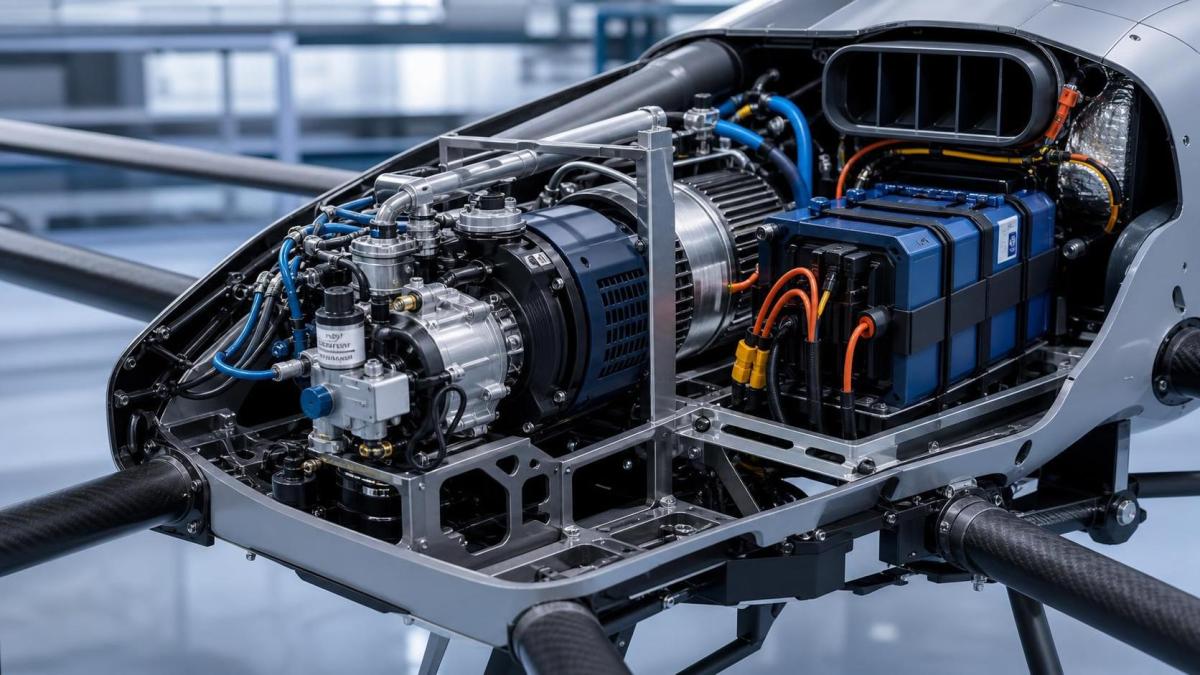
Generator weight directly reduces the mass available for sensors, cargo, fuel, redundant avionics, or battery reserve. Yet the practical weight impact is larger than the generator’s catalog mass. The installed system may include an engine coupling, mounting frame, vibration isolators, fuel plumbing, exhaust components, cooling ducts, electronic control hardware, rectifier or inverter modules, wiring, shielding, and protective structure. A comparison based on the bare generator can materially understate the integration penalty.
Center of gravity is equally important. A compact generator mounted far from the aircraft’s center of mass may require structural reinforcement or repositioning of fuel tanks and payloads. As fuel burns, the aircraft’s balance changes. If the generator and fuel system are not considered together, an apparently acceptable component layout can create unacceptable trim demand or reduce control margin during late-mission flight.
Specific power, often expressed as watts per kilogram, is a useful screening metric but not a final selection criterion. A lighter generator with lower continuous output stability may require a larger battery, heavier cabling, or more extensive thermal management. Conversely, a somewhat heavier unit may reduce the need for auxiliary energy storage or offer a more favorable installation architecture. The decision should be based on total installed mass and its effect on mission payload, rather than the mass of one component in isolation.
- Calculate mass at the system level: generator, mounts, cooling, power electronics, wiring, fuel interfaces, and protective hardware.
- Model the center of gravity at full fuel, mid-mission fuel, and reserve-fuel conditions.
- Include the battery mass required for transients, emergency descent or recovery, and generator-out response.
- Check whether structural reinforcement offsets the apparent advantage of a compact component.
Fuel consumption should be evaluated by mission energy, not hourly marketing claims
Fuel consumption is often presented as liters per hour, but that figure has little value without a load point, fuel type, ambient condition, and engine speed. A better measure is fuel consumed per unit of useful electrical energy at the relevant duty cycle. Even then, the aircraft’s overall endurance depends on fuel tank mass, fuel system losses, generator efficiency, battery cycling losses, and reserve requirements.
For example, a lower fuel burn at an ideal steady-state test point does not automatically produce longer flight time. If the generator responds slowly to mission load changes, the battery may cycle more deeply and more frequently. That can introduce conversion losses, increase battery temperature, and require a larger battery pack. The effective mission energy balance may be worse than the supplier’s engine data suggests.
Fuel type also creates operational consequences. Aviation gasoline, heavy fuel, gasoline-oil mixtures, and other fuel options have different storage, transport, ignition, cold-start, maintenance, and regulatory implications. A fleet operating from remote industrial sites may prioritize fuel commonality with other field equipment. A defense or maritime program may prioritize logistics compatibility or lower fire risk. These choices should be reviewed with the operator, not left to the powertrain team alone.
Fuel quality tolerance deserves specific attention. Field operations may expose equipment to moisture contamination, inconsistent fuel batches, dust, temperature extremes, and long storage periods. A generator-engine package that performs well with clean laboratory fuel can become a maintenance problem when deployed through a distributed service network. Suppliers should be asked about filtration requirements, permissible storage conditions, cold-start limits, and the effect of fuel variation on output and service life.
Thermal behavior can decide whether the rated output is usable
UAV installations are thermally constrained. Unlike ground equipment, an aircraft may have limited space for cooling air, little tolerance for open enclosures, and stringent aerodynamic requirements. Generator losses, engine heat, exhaust heat, power conversion losses, and battery heat can accumulate in the same small volume. A component that reaches its rated output on an open test stand may be derated significantly inside a fuselage.
Thermal evaluation must include the entire flight envelope. High ambient temperature, high density altitude, slow loiter speed, enclosed payload bays, and restricted airflow during climb can all reduce available cooling. In cold conditions, the opposite issue can arise: fuel vaporization, lubricant viscosity, battery charge acceptance, and condensation management may affect startup and stable operation.
Thermal runaway is usually associated with batteries, but the broader power system deserves the same discipline. Hot connectors, undersized conductors, marginal insulation, poorly controlled exhaust routing, and inadequate separation between fuel lines and electrical components can all create system risks. The evaluation should identify the hottest expected operating condition and demonstrate that generator output, voltage regulation, and protective functions remain within acceptable limits at that point.
Do not accept “air-cooled” as a complete thermal strategy. Request installation guidance, required airflow, allowable inlet temperature, temperature sensor locations, derating curves, and shutdown thresholds. If these are unavailable, the integration team should plan instrumented ground and flight tests before making volume commitments in the airframe.
Reliability is about failure behavior, not only service life
For technical evaluators, reliability claims should be translated into operational questions. What happens if the generator output falls below demand? Does the battery automatically maintain the propulsion bus? Is there enough reserve energy to execute a controlled return, diversion, or landing? How are faults detected, logged, and communicated to the flight controller and ground station?
A hybrid UAV requires clear power-management logic. In a well-designed architecture, the generator supplies the planned cruise energy, the battery handles rapid changes and provides emergency reserve, and the system continuously monitors voltage, current, temperature, rotational speed, insulation condition where applicable, and fuel status. A fault should result in a defined degraded mode rather than an uncontrolled sequence of voltage collapse, battery depletion, and forced landing.
Maintenance intervals should be evaluated in the context of fleet utilization. An industrial inspection contractor flying frequently may value predictable, short service actions more than theoretical component life. A remote operation may need line-replaceable modules, diagnostic access, and a realistic spare-parts plan. The generator itself may be only one source of downtime; connectors, couplings, controllers, fuel pumps, and vibration-damaged wiring often deserve equal scrutiny.
Vibration is particularly important when an internal-combustion engine is part of the system. It can affect sensor accuracy, fastener retention, wire harness durability, bearings, avionics reliability, and image quality. A generator with favorable electrical performance may still be unsuitable if its mounting arrangement transfers unacceptable vibration into the payload or airframe. The integration review should include vibration spectra, isolator behavior across engine speed, and the risk of resonance with structural members or sensor mounts.
Payload trade-offs need to be expressed in mission outcomes
“More generator power means less payload” is directionally true but incomplete. The relevant trade-off is between energy capability and mission value. A heavier power system may enable a larger sensor, longer dwell time, stronger communications link, or more reliable operation in cold weather. A lighter system may allow greater payload mass but reduce endurance or restrict the use of active payload functions.
For a pipeline inspection mission, the decisive measure may be kilometers inspected per sortie with the required sensor quality. For maritime monitoring, it may be time on station at a specified distance from launch. For an industrial site survey, it may be the number of payload operating hours achievable before fuel reserve is reached. Converting component choices into these mission metrics prevents a selection process from becoming overly focused on individual specifications.
A practical comparison should model at least three scenarios: nominal mission, high-demand mission, and degraded operation. The nominal scenario establishes efficiency. The high-demand scenario tests peak power, thermal margin, and battery buffering. The degraded scenario tests whether a generator fault, high ambient temperature, or reduced fuel availability still permits safe recovery. A proposal that performs well only in the nominal model carries more operational risk than its headline endurance figure suggests.
Supplier evaluation should include integration evidence
Component availability is not the same as integration readiness. A supplier may have a capable generator but limited experience with aircraft vibration, electromagnetic compatibility, altitude operation, or safety-critical fault handling. For an industrial UAV program, evaluators should distinguish between a development component and a repeatable production solution.
Relevant supplier questions include:
- What electrical output is demonstrated continuously at the required voltage and expected ambient conditions?
- Which ratings are measured at the generator terminals, and which include the complete regulated power system?
- What installation conditions are necessary to achieve the stated output?
- How does the unit respond to defined load steps, and what battery buffering is assumed?
- What are the documented maintenance intervals, consumable parts, and recommended inspection procedures?
- What test evidence exists for vibration, thermal cycling, electromagnetic compatibility, and endurance?
- What configuration controls apply to production units, firmware, controllers, and replacement parts?
- What support is available during flight-test integration and failure analysis?
Certification and compliance requirements depend on the aircraft category, operating jurisdiction, mission, and whether the system is intended for civil, public-sector, or defense use. Requirements may involve airworthiness expectations, radio-frequency behavior, fuel handling, transport of hazardous materials, emissions, noise, and operational approvals. Specific standards and approvals should be verified against the intended deployment location and aircraft program; they should not be inferred from a generator supplier’s general marketing statements.
A disciplined selection process reduces expensive redesigns
The strongest selection process is usually phased. First, define the mission energy and peak-load envelope. Next, establish aircraft mass, volume, center-of-gravity, and thermal constraints. Then compare generator candidates using installed-system mass, continuous usable output, fuel use at actual load points, transient response, maintenance requirements, and fault behavior. Only after this screening should the team commit to detailed mechanical and electrical integration.
Ground tests should reproduce realistic electrical loading rather than using a fixed resistive load alone. The test setup should include representative propulsion demand, payload cycling, battery charge and discharge behavior, expected cabling, and cooling constraints. Flight testing then validates the parts of the model that are hardest to predict: airflow, vibration, radio-frequency interaction, altitude effects, fuel slosh, and operator procedures.
The most important question is not whether a UAV generator can produce enough power in isolation. It is whether the complete aircraft can deliver the required mission, with usable payload and credible recovery margin, over the conditions its operator will actually face. When evaluators frame the decision that way, power output, weight, fuel consumption, and payload capacity become connected variables rather than competing catalog specifications.
Contact Us