Precision engineering for demanding UAV operations



What Is a UAV Generator and How Does It Support Long-Endurance Drone Missions?
A UAV generator is an onboard electrical power source that converts stored fuel or another primary energy supply into electricity during flight. It is used when a drone must remain airborne longer than a battery-only configuration can reasonably support. Rather than relying entirely on a battery pack that steadily depletes from takeoff, the aircraft can generate electrical power continuously and use a battery as a buffer for peak demand, reserve energy, or emergency landing.
In a long-endurance aircraft, power is required by far more than the propulsion motor. Flight-control computers, navigation equipment, servos, communications links, cameras, thermal imagers, radar units, data recorders, payload release mechanisms, and environmental heaters may all draw power. A properly integrated generating system supplies these loads within a controlled voltage range while the aircraft experiences vibration, altitude changes, temperature shifts, and rapid changes in throttle setting.
How onboard generation changes the energy system
A conventional battery-powered multirotor or fixed-wing drone carries all of its usable electrical energy at takeoff. Flight duration depends on battery capacity, payload mass, aerodynamic efficiency, weather, and the required reserve. Adding battery capacity can increase available energy, but it also adds mass. At some point, the additional battery weight consumes much of the extra energy benefit.
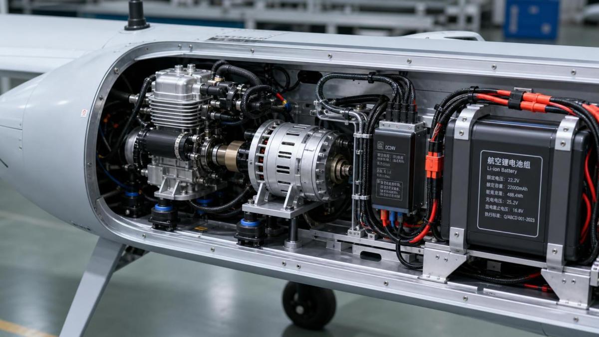
An onboard generator changes that relationship. Fuel commonly has a higher energy density by mass than current rechargeable batteries, although the conversion process is not perfectly efficient and requires additional machinery. A generator-based system therefore includes the energy source, a fuel tank or storage vessel, an engine or other prime mover, an electrical generator, power electronics, cooling components, mounts, wiring, and usually a rechargeable battery.
The battery remains important. It can deliver immediate current when motors accelerate, maintain power while the generator starts, absorb short load spikes, and provide a controlled response if generation is interrupted. In many designs, the generator is sized for the sustained electrical demand rather than for every brief peak. The battery then covers transient demand that would otherwise require a larger, heavier generator.
This architecture is most often associated with fixed-wing unmanned aircraft and hybrid vertical-takeoff aircraft, where efficient cruise flight can make extended endurance practical. Multirotor platforms can also use onboard generation, but hovering requires substantial continuous power, so mass, vibration, and thermal management become particularly restrictive.
Core components and the power path
At the center of a typical combustion-based UAV generator is a compact internal-combustion engine coupled to a permanent-magnet alternator. The engine turns the alternator rotor, and the alternator produces electrical power that varies with rotational speed and load. A rectifier and voltage-regulation stage convert this output into stable direct current suitable for the aircraft power bus.
The power electronics must handle more than simple conversion. They may regulate voltage, limit current, isolate faults, control battery charging, filter electrical noise, report operating data to the flight-control system, and prevent reverse current from the battery into the generator. In higher-power arrangements, a motor controller may also coordinate propulsion demand with the generator and battery so that neither source is pushed outside its safe operating range.
Several technical terms are useful when comparing systems:
- Continuous electrical output is the power the system can deliver for sustained operation under defined conditions. It is more relevant to endurance than a short peak rating.
- Voltage range must match the aircraft bus and downstream converters. A nominal voltage alone is insufficient because loads must tolerate charging and load-transition limits.
- Specific power compares output against system mass. It should include mounts, exhaust parts, cooling hardware, and control electronics rather than the engine alone.
- Fuel consumption at load indicates how much fuel the prime mover uses at a specified output. Consumption figures without output, atmospheric condition, or operating point are difficult to compare.
- Power quality describes voltage stability, ripple, electrical noise, and the system response when a payload or propulsion load changes suddenly.
Fuel delivery is another system-level issue. A tank, venting arrangement, lines, filters, pump where required, and shutoff valve must continue working across the aircraft's expected attitudes. Fuel pickup location matters because a steep climb, turn, or deceleration can move liquid away from the pickup. Filters must be accessible, while routing must avoid abrasion points, hot exhaust surfaces, and electrical connectors.
Matching generation to the mission load
Generator sizing begins with an electrical load profile rather than a single maximum-power number. The profile should distinguish between continuous cruise demand, intermittent payload demand, takeoff or climb demand, startup current, and the power needed for avionics and communications throughout the mission. A camera gimbal may use modest steady power but produce short movement peaks. A heated sensor may draw little during warm weather and considerably more in cold conditions. Data transmission equipment can also change consumption with link quality and output setting.
For a fixed-wing aircraft, propulsion demand often falls after climb and stabilizes during cruise. This can allow a generator to cover cruise power while the battery supports climbing, maneuvering, or go-around conditions. The control strategy needs clear boundaries: when the battery is charged, when it is allowed to discharge, what happens when demand exceeds generation, and what reserve remains available for a landing sequence.
Generator output should not be treated as fully available under every condition. Air density, cooling airflow, fuel characteristics, elevation, engine wear, and enclosure temperature may reduce usable output. A system that appears adequate on a bench can become marginal inside a tightly packaged airframe on a hot day. Electrical conversion losses also matter. Alternators, rectifiers, DC-DC converters, wiring, and battery charging each dissipate some energy as heat.
Wire selection is tied to both current and installation geometry. Conductors that are too small create voltage drop and heat, especially along long paths between generator, battery, distribution board, and propulsion controllers. Larger cable adds mass. Connectors require positive retention, appropriate current capacity, insulation compatible with heat and fuel exposure, and strain relief so vibration is not transferred directly to terminals.
Mechanical integration is as important as output
An onboard generating set is a vibrating, heat-producing rotating machine attached to a lightweight aircraft structure. Installation quality can determine whether the electrical design performs reliably. The mounting arrangement must distribute load into the airframe without concentrating stress in thin composite skins or unsupported printed parts. Aluminum brackets are common where stiffness and heat resistance are needed; carbon-fiber structures may require insulating layers or careful interface design because carbon fiber can be electrically conductive and can promote galvanic corrosion when paired directly with certain metals in wet conditions.
Vibration isolators can reduce transmission into avionics and cameras, but excessively soft mounts may let the generator move, shift the center of gravity, fatigue hoses, or misalign a belt or coupling. The selected isolator stiffness should reflect generator mass, engine speed range, expected accelerations, and the airframe's structural modes. A practical installation also keeps fasteners accessible for torque inspection and uses locking methods appropriate to the temperature and vibration environment.
Cooling cannot be left to residual airflow. An engine, alternator, regulator, exhaust, and battery each have different temperature limits. Ducted cooling may need an inlet, a defined path across hot surfaces, and an outlet with enough pressure difference to move air. Merely placing vents near a heat source does not guarantee airflow through it. Exhaust routing needs adequate clearance from polymer parts, wiring insulation, fuel lines, and composite laminates. Heat shielding may be necessary, but shielding also traps heat unless the overall flow path is considered.
Center-of-gravity control remains a flight issue. Fuel mass changes during a mission, so tank placement can alter balance as fuel is consumed. The generator, tank, battery, and payload should be assessed together at full and near-empty fuel conditions. A configuration that balances correctly only at takeoff may require excessive control effort later in flight.
Reliability depends on fault behavior
Long endurance is useful only when the power system has predictable behavior during abnormalities. A generator may lose output because of fuel starvation, overheating, ignition problems, belt or coupling failure, wiring damage, regulator faults, or sensor errors. The aircraft should have a defined electrical response for each plausible event. In many hybrid configurations, the battery supplies enough reserve for stabilization, navigation, communications, and a controlled recovery sequence after generation stops.
Electrical protection commonly includes fuses or circuit breakers, overcurrent limits in power controllers, temperature monitoring, battery management functions, and voltage thresholds that trigger a change in flight mode. The protection scheme must be coordinated. A fuse that opens too slowly may not protect a conductor; one selected too close to a normal transient load may create nuisance interruptions. Fault isolation is also useful: a failed payload should not necessarily remove power from flight-critical controls.
Electromagnetic interference deserves attention because ignition systems, alternators, switching regulators, telemetry radios, GNSS receivers, and imaging payloads can affect one another. Shielded cable, twisted-pair wiring for sensitive signals, grounding strategy, physical separation, filters, and enclosure bonding can all contribute to a quieter installation. The exact treatment depends on the aircraft architecture. Connecting every shield at random can create unwanted current paths, while leaving shielding unbonded may provide little protection.
Verification before field deployment
Bench testing should represent the aircraft electrical load as closely as practical. It is useful to observe cold starts, warm restarts, generator output at different loads, battery charging behavior, voltage ripple, temperature rise, and the transition between generator and battery supply. Test instruments should record rather than merely display values, since brief voltage dips or thermal excursions may be missed during visual observation.
After bench work, installed testing can reveal issues hidden by an open test stand. Covers change cooling; installed exhaust routing changes back pressure and heat transfer; wiring lengths change voltage drop; and the aircraft structure changes vibration behavior. Ground runs should include inspection for fastener movement, fuel seepage, hose rubbing, connector loosening, abnormal noise, and heat effects on nearby components.
Flight testing normally progresses from short, low-risk profiles to longer operation after the power system has shown stable behavior. The purpose is not simply to demonstrate a long flight. It is to observe electrical margins, fuel behavior through maneuvers, thermal stabilization, vibration effects on sensors, and reserve response under representative loads. Any change to the payload, propeller, enclosure, software settings, or fuel system can alter these results.
Maintenance and practical limits
A UAV generator introduces maintenance tasks that battery-only aircraft may not have. These can include inspecting spark ignition components, fuel filters, hoses, seals, cooling passages, bearings, couplings, exhaust hardware, vibration mounts, and electrical terminals. Service intervals should follow the specific engine and component documentation, while actual inspection frequency may need adjustment for dust, humidity, salt exposure, cold weather, or repeated high-load operation.
Fuel handling also affects reliability. Contamination, water ingress, unsuitable storage conditions, or incorrect fuel mixture where applicable can lead to poor starting, unstable output, or internal damage. Fuel containers and transfer tools should be kept clean and clearly controlled. The aircraft should be stored with consideration for the fuel system, battery state, and the possibility of vapor, leakage, or corrosion during downtime.
A common misunderstanding is that an onboard generator automatically removes endurance constraints. It shifts the limiting factors. Fuel capacity, aircraft aerodynamics, engine reliability, cooling, payload demand, weather, communications range, reserve policy, and maintenance condition still define the usable mission window. Another misconception is that the generator can replace all battery capacity. In practice, the battery often provides the fast electrical response and fault reserve that make the hybrid system workable.
The most useful way to assess a UAV generator is as part of the complete aircraft energy architecture. Output rating, mass, fuel consumption, voltage control, cooling, vibration isolation, wiring, battery behavior, and recovery strategy need to agree with one another. When those interfaces are treated as engineering requirements rather than accessories, onboard generation can support missions that require sustained airborne electrical power beyond the practical limits of batteries alone.
Contact Us