Precision engineering for demanding UAV operations



Key UAV Generator Safety Standards for Fuel Systems, EMI, and Flight Integration
Why Generator Safety Is a Flight-Safety Question
An onboard UAV generator is often evaluated first as a power source: Can it deliver enough continuous output? Does it fit the aircraft’s weight and endurance targets? What is its fuel consumption at cruise load?
Those questions matter, but they are not sufficient for quality-control or safety teams. A generator-based power system can meet its rated output in a bench test and still create an unacceptable aircraft risk through fuel leakage, hot-surface ignition, conducted electrical noise, radio-frequency interference, vibration-induced damage, or unstable interaction with the flight-control power architecture.
For industrial UAV operations, the practical question is not whether a generator is “certified” in the abstract. It is whether the complete installation has evidence appropriate to the intended mission, operating environment, aircraft category, and local regulatory framework. This distinction becomes especially important for long-endurance inspection, logistics, public-safety, offshore, mining, and beyond-visual-line-of-sight operations, where a power-system failure may not be recoverable by an immediate landing.
A useful starting point is to treat the UAV generator as a safety-critical subsystem with five connected boundaries: fuel containment, ignition and thermal control, electrical quality, electromagnetic compatibility, and flight-system integration. Weakness at any one boundary can undermine an otherwise capable generator.
There Is No Single “UAV Generator Certificate”
Buyers sometimes expect a generator supplier to provide one certificate that resolves airworthiness, safety, and operational approval. In most markets, that is not how compliance works. A component-level test report, an engine emissions document, a battery safety report, or a general CE declaration may all be relevant, but none independently proves that the generator is safe on a particular aircraft.
The applicable requirements usually sit across several layers:
- National aviation rules: These determine how the UAV operation is classified and what approval, operating limitation, maintenance process, or safety case is required. In the United States, FAA requirements and approvals may be relevant; in Europe, the EASA framework and national implementation may apply. The exact path depends on the operation rather than generator type alone.
- Aircraft-level airworthiness or design-assurance expectations: These address hazards, redundancy, failure conditions, controllability, and safe continuation or termination of flight.
- Environmental and electromagnetic test standards: RTCA DO-160 is widely used as a reference for airborne equipment environmental qualification, including temperature, vibration, power input, and electromagnetic effects. Its use must be tailored to the installation and is not automatically proof of airworthiness.
- Component and process controls: Fuel hardware, wiring, electronic controls, pressure vessels, connectors, and software may each require their own evidence, traceability, and inspection criteria.
- Local safety, transport, environmental, and workplace rules: Fuel storage, hazardous-area practices, noise, emissions, and maintenance-site controls can affect deployment even where aviation approval is addressed separately.
For a quality team, the important discipline is to map each claim to its scope. “Tested to DO-160,” for example, should lead to follow-up questions: Which sections? At what categories and severity levels? Was the unit tested in its aircraft installation or as a standalone item? Were later changes made to the exhaust, wiring harness, electronic control unit, or mounting system?
Claims that do not specify configuration, test condition, and acceptance criteria are difficult to use in a release decision.
Fuel-System Integrity: Control the Leak, the Vapor, and the Ignition Source
Fuel-system safety is more than selecting a tank with a nominally compatible material. A UAV installation has unusual constraints: compact packaging, changing attitude, vibration, pressure variation with altitude, limited separation between fuel and electronics, and frequent field servicing. These conditions can turn small design weaknesses into recurrent operational defects.
Inspection should begin with the complete fuel path, not just the tank. That includes fill point, cap, venting arrangement, pickup, lines, filters, pumps, regulators, shutoff valves, injectors or carburetion hardware, fittings, clamps, drain points, and return lines where used. Every joint is a potential leak point; every low point can collect fuel; every line near an exhaust component or alternator can become a heat and ignition concern.
Key verification points include:
- Fuel-line material compatibility with the specified fuel blend, including anticipated ethanol content or other additives.
- Resistance of hoses, seals, and fittings to temperature cycling, ultraviolet exposure where relevant, and vibration.
- Protection against chafing at bulkheads, clamps, frame interfaces, and service-access areas.
- Vent performance across expected altitude, temperature, and aircraft-attitude conditions, without creating a liquid fuel discharge path.
- Positive fuel shutoff behavior after commanded shutdown, crash detection where applicable, and electrical fault conditions.
- Physical separation or shielding between fuel components and exhaust surfaces, high-current wiring, sparking contacts, and ignition components.
- Clear inspection access, drainability, and maintenance instructions rather than designs that conceal fittings behind permanent structural panels.
Pressure testing can identify assembly leaks, but it does not fully simulate flight. A robust validation plan combines pressure and leak checks with vibration exposure, temperature cycling, representative attitude testing, and post-test inspection. When possible, the test configuration should include production-intent hose routing, clamps, protective sleeves, and mounting brackets. A test using short, straight bench hoses does not validate a routed aircraft installation.
Fuel quantity and starvation behavior also deserve attention. Long-endurance missions can operate at changing load profiles, while fuel slosh or pickup unporting may occur during turns, climbs, descents, or gust response. The generator must not merely keep running in steady level flight; the aircraft must demonstrate a defined response to low-fuel and transient fuel-supply conditions.
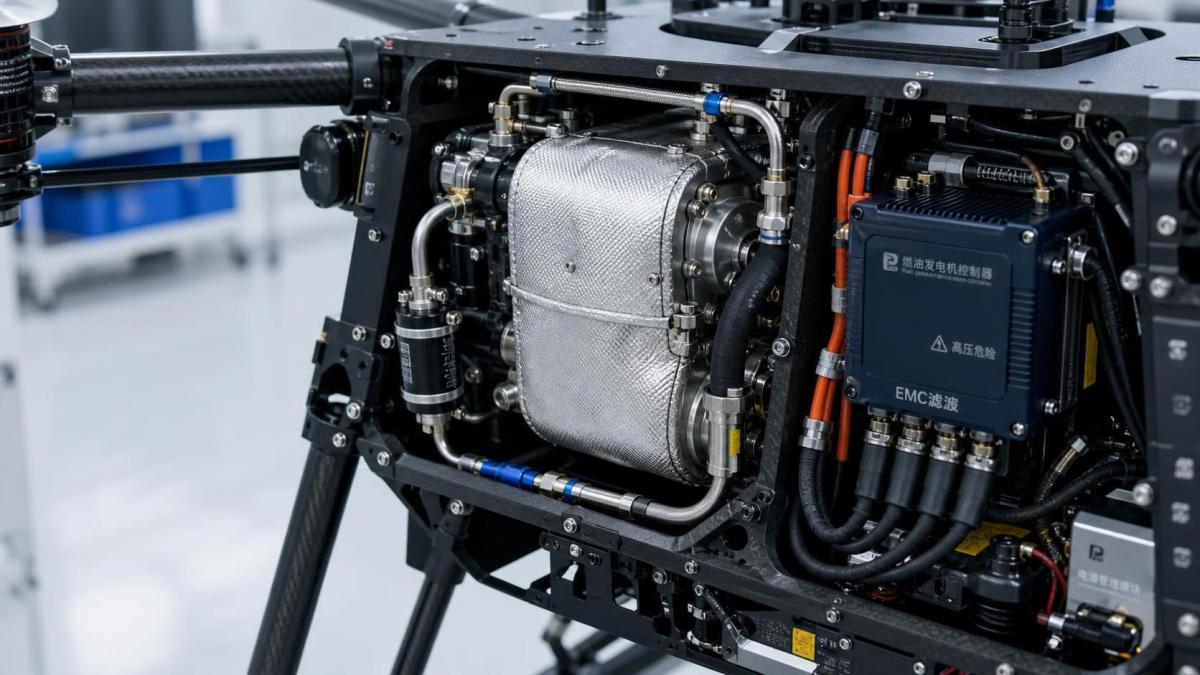
Thermal Protection Must Address the Entire Heat Path
Internal-combustion generator systems create several heat sources: the engine block, exhaust, catalytic components where fitted, generator windings, rectifier or inverter electronics, regulators, and battery-charging circuits. The relevant risk is not simply the maximum exhaust temperature. It is the temperature reached by nearby materials, wiring insulation, fuel lines, avionics, composite structure, and the enclosure during the most demanding credible mission condition.
Quality reviews should ask for thermal mapping under realistic combinations of high ambient temperature, reduced cooling airflow, maximum continuous electrical load, climb or hover demand, and partial enclosure blockage. Ground runs alone can be misleading. Some airframes receive less cooling on the ground, while others experience recirculation or local hot spots only in flight.
The following conditions should be deliberately tested or assessed:
- Cooling-fan failure, partial inlet blockage, and contamination of cooling paths by dust or debris.
- Exhaust loosening, deformation, or leakage after vibration exposure.
- Heat soak after landing, when airflow stops but engine and exhaust components remain hot.
- Temperature exposure of adjacent battery packs, especially where batteries provide start power, transient buffering, or emergency reserve energy.
- Response to sensor faults, over-temperature events, and loss of a cooling-related electrical supply.
Automatic shutdown is valuable, but it is not a complete thermal strategy. A shutdown threshold may prevent component destruction while still causing abrupt loss of aircraft propulsion or flight-control power. The aircraft safety assessment should define what happens next: whether battery reserve takes over, whether the system reduces load progressively, whether the aircraft enters a controlled return mode, and how much energy margin remains.
EMI Is Often Found Late, When It Is Most Expensive to Fix
Generator systems can introduce electromagnetic interference through ignition circuits, alternator switching, inverters, voltage regulators, brush assemblies, high-current cabling, and poorly bonded enclosures. The risk is not limited to obvious radio interference. Noise can affect GNSS reception, compass performance, telemetry links, remote identification equipment, payload sensors, barometric readings, data buses, and the flight controller’s power supply.
One common misunderstanding is that a stable voltage display proves electrical compatibility. It does not. A power bus can have an acceptable average voltage while carrying ripple, spikes, ground noise, or transient disturbances that degrade electronics intermittently. These events may only appear at certain engine speeds, loads, cable temperatures, or radio transmission states.
RTCA DO-160 provides a widely recognized framework for evaluating environmental and electromagnetic effects on airborne equipment. Relevant sections may include conducted and radiated emissions, susceptibility, power-input behavior, voltage spikes, vibration, temperature, humidity, and other environmental conditions. However, test categories must be selected based on the actual aircraft environment. A generic report without category information has limited decision value.
For UAV generator integration, a practical EMI verification program should include:
- Baseline measurements with the generator off, then comparison across idle, nominal cruise, peak electrical load, and rapid load transitions.
- GNSS position-quality and satellite-lock monitoring, including checks for interference with antennas located near ignition leads, inverter housings, or exhaust assemblies.
- Compass calibration and in-flight heading verification with the generator operating at representative speeds.
- Telemetry, command-and-control link, remote-ID, and payload data-link performance under electrical load.
- Inspection of grounding, bonding straps, cable shielding terminations, connector backshells, and separation between noisy power conductors and signal wiring.
- Transient testing for starting, shutdown, load shedding, battery connection, regulator failure modes, and emergency transfer to reserve power.
Automotive electromagnetic standards, such as CISPR-based vehicle tests, may offer useful engineering evidence for certain subcomponents, but they should not be assumed to represent the electromagnetic environment of a specific aircraft. Likewise, compliance with a consumer or industrial electronics marking scheme does not establish compatibility with flight-critical avionics.
Vibration, Fastener Retention, and Fatigue Are Configuration Problems
Generators combine rotating machinery, combustion pulses, airframe resonance, and changing propeller loads. The resulting vibration profile can loosen fasteners, fatigue brackets, crack exhaust supports, damage circuit boards, wear wire insulation, and cause intermittent connector faults. A mount that performs well on one airframe may fail on another because the structural response is different.
Vibration qualification should therefore consider both the generator assembly and the aircraft installation. DO-160 vibration testing is often referenced for airborne equipment, while MIL-STD-810 may be used in industrial or defense-oriented programs. Neither reference should be treated as a substitute for installation-specific evidence. Test severity, axis, frequency range, duration, fixture design, and functional monitoring all affect the value of the result.
After vibration and endurance testing, inspection should extend beyond visible damage. QC teams should examine torque retention, safety-wire or locking-feature condition, bracket deformation, elastomer mount compression, connector engagement, wire chafing, fuel-line rub points, heat-shield movement, and electrical continuity. A post-test functional run is necessary, but it should not replace a detailed physical teardown or inspection protocol.
Flight Integration Defines the Real Failure Consequence
The most important safety question is often missed during component procurement: What does the aircraft do when generator output becomes degraded, unstable, or unavailable?
A generator may be the primary electrical source, a range extender charging a battery, a direct support for propulsion loads, or an auxiliary supply for payloads. Each architecture creates different hazards. In a hybrid system, a generator fault may be manageable if a battery has verified reserve capacity and the energy-management controller transitions cleanly. In another design, a sudden voltage drop may reset the flight controller or trigger uncontrolled load shedding.
The integration review should define credible faults and required aircraft responses. These include engine stoppage, fuel starvation, over-temperature trip, over-voltage, under-voltage, regulator failure, broken ground connection, intermittent connector, sensor failure, ECU reset, and unexpected load demand. For each fault, the team should document detection method, annunciation, automatic action, pilot or operator awareness, available reserve energy, and expected landing or recovery outcome.
Particular attention is needed where a common cause can defeat both the generator and its backup. Examples include a shared power-distribution board, a battery exposed to generator heat, a single connector carrying both control and charging paths, or software that depends on generator telemetry to make battery-management decisions. “Redundant battery” is not meaningful if the redundant path shares the same unprotected failure mechanism.
What to Request Before Accepting a Supplier Claim
For procurement and incoming-quality decisions, a well-organized evidence package is generally more useful than a broad statement that the product is “aviation grade.” The package should identify the exact model, revision, firmware, fuel specification, installation limits, and tested configuration.
A practical request list includes a hazard or failure-mode analysis; fuel-system drawings and material specifications; environmental and EMI test reports with stated methods and acceptance criteria; thermal and vibration test records; electrical schematics; transient and fault-response data; software and firmware revision control where applicable; production inspection records; serial-number traceability; maintenance intervals; and configuration-change notification procedures.
It is also reasonable to ask which evidence is supplier-generated, which is independently witnessed, and which has been reproduced on the intended airframe. The goal is not to demand paperwork for its own sake. It is to identify whether the supplier’s evidence addresses the same risks created by the planned mission.
For safety managers, the final decision should connect technical evidence to operational controls: preflight leak checks, fuel handling procedures, hot-work restrictions, maintenance release criteria, spare-part traceability, post-hard-landing inspections, incident reporting, and removal-from-service thresholds. A UAV generator becomes dependable through this combination of design evidence, controlled production, installation validation, and disciplined field operation.
The central lesson is straightforward: rated power is only the beginning. The generator should be accepted as part of the aircraft’s safety case only after its fuel, heat, vibration, emissions, electrical behavior, and failure response have been examined as one integrated system.
Contact Us