Precision engineering for demanding UAV operations



Why Does a UAV Generator Lose Power at Altitude or in Extreme Temperatures?
Why Does a UAV Generator Lose Power at Altitude or in Extreme Temperatures?
When a UAV generator loses power at high altitude or in extreme heat and cold, the cause is rarely a single failed component. A generator that appears stable on a workshop bench may struggle once it is installed in a thin-air mountain environment, a hot enclosed payload bay, or a cold launch site. The usual complaint is simple—reduced electrical output, unstable voltage, slow recovery after load changes, or an unexpected shutdown—but the troubleshooting path is not.
For after-sales maintenance work, the key is to separate an environmental derating issue from a genuine mechanical, fuel, ignition, cooling, or control-system fault. Altitude and temperature do not merely “make the engine work harder.” They change combustion quality, air intake mass, fuel behavior, lubrication resistance, cooling performance, battery support, and the operating assumptions built into the generator controller.
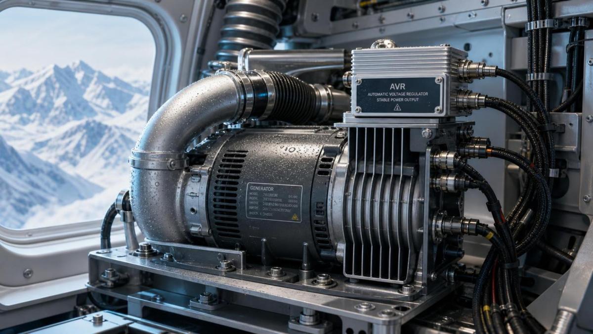
This is especially important for compact engine-driven UAV power systems, where the generator, engine, rectifier, voltage regulator, wiring harness, and airflow path are tightly packaged. A small loss in one area can become a much larger system-level problem once the aircraft demands peak power.
At Altitude, the Generator Is Usually Short of Air Mass, Not Just Air
The most direct reason for altitude-related power loss is reduced air density. As altitude rises, the engine draws in less oxygen for the same intake volume. If the fuel system continues delivering fuel as though the engine were operating near sea level, the air-fuel mixture becomes richer than intended. Combustion efficiency drops, exhaust temperature behavior may change, throttle response becomes less clean, and the engine may no longer produce enough shaft power to maintain electrical output under load.
This is not always obvious during a no-load run. A UAV generator can start normally, idle normally, and even show acceptable voltage before the electrical load rises. The weakness often appears during climb demand, payload activation, battery charging, or a transient load event. The controller requests more power, but the engine cannot generate the required torque without more available oxygen. Frequency, RPM, voltage, or DC bus stability may then drift depending on the system architecture.
Naturally aspirated engines are generally more sensitive because they depend on ambient pressure to fill the cylinder. A turbocharged or supercharged system can compensate to a degree, but it introduces its own limits: compressor performance, boost control, intake-air temperature, exhaust backpressure, and calibration boundaries. A turbocharger is not a guarantee that power will remain unchanged at all operating elevations.
Maintenance teams should therefore avoid treating every altitude complaint as a carburetor, injector, or alternator fault. Before replacing parts, confirm the operating elevation, ambient temperature, load profile, propulsive demand, and whether the installed generator configuration has an approved derating curve or altitude-specific calibration. If that information is unavailable, the realistic output limit needs to be established through controlled testing rather than guesswork.
The intake system deserves closer inspection than it usually gets
At sea level, a partially restricted filter or slightly distorted intake duct may not cause a noticeable complaint. At altitude, that same restriction can push the system beyond its usable margin. Check for collapsed flexible ducts, loose clamps, blocked intake screens, contaminated filters, and poorly routed air inlets that draw heated air from inside the fuselage rather than cooler outside air.
An intake leak can be equally misleading. On electronically controlled fuel-injected systems, unmetered air may result in unstable correction behavior. On carbureted engines, mixture adjustment that seemed acceptable at one elevation may be unsuitable at another. The repair is not necessarily “lean it out” or “replace the carburetor.” The correct action depends on how the fuel system measures airflow, temperature, pressure, and throttle position.
Extreme Heat Reduces Power and Can Also Create a Cooling Problem
High ambient temperature affects the UAV generator in two competing ways. Hot air is less dense, so the engine receives less oxygen per intake stroke. At the same time, the engine, alternator, power electronics, and voltage regulator have less temperature margin for rejecting heat. In a compact UAV installation, the second effect can be just as serious as the first.
A common field pattern is that output remains acceptable immediately after startup but falls after several minutes at a sustained load. That pattern should raise suspicion of heat soak, not just fuel mixture. The generator housing may be receiving insufficient cooling airflow, or hot exhaust air may be recirculating toward the intake and electronics. A shroud that is slightly misplaced, a cooling passage obstructed by dust, or a damaged seal around an access panel can alter airflow significantly in a tightly enclosed compartment.
Fuel delivery becomes less forgiving in heat as well. Fuel lines routed close to exhaust components or hot cylinder surfaces may absorb enough heat to affect vapor handling, pressure stability, or pump behavior. The symptom can resemble ignition failure: intermittent surging, hesitation under load, or a sudden power dip followed by recovery. Do not replace coils or injectors until fuel pressure, line routing, filter condition, tank venting, and thermal shielding have been checked under representative temperature conditions.
Electrical components also have thermal limits. Rectifiers, regulators, connectors, and wiring may pass a brief bench test while becoming unstable after heat exposure. Look for discoloration at terminals, hardened insulation, increased connector resistance, loose ground points, and signs that a regulator is reducing output to protect itself. If the engine speed remains stable while DC output declines, the mechanical side may be healthy and the electrical conversion stage deserves priority attention.
Cold Conditions Create Different Failures, Often Before Takeoff
Cold-weather power loss is often blamed on “a weak generator,” but many cases begin with starting and warm-up behavior. Cold oil increases resistance during cranking and early operation. Fuel atomization can worsen. Batteries provide less available support. If the generator control system depends on a battery for excitation, ECU operation, fuel pumping, or initial stabilization, low battery voltage can create an unstable sequence before the engine reaches a usable operating condition.
A unit that starts but cannot accept load immediately may not have a failed alternator. It may simply need a defined warm-up period, provided that the manufacturer’s operating instructions allow it. The important distinction is whether output improves in a predictable way as temperatures stabilize, or whether the instability remains after the engine and electronics are warm. Persistent faults after warm-up point more strongly toward ignition, fueling, sensor, wiring, or regulation issues.
Cold also exposes moisture problems. Condensation can form when equipment moves between storage, transport, and outdoor operating temperatures. Water contamination in fuel, damp connectors, icing around intake openings, and moisture inside sensor housings can all produce intermittent symptoms. These faults are frustrating because they may disappear once the unit is brought indoors. A visual inspection alone is not enough; technicians should inspect drain points, connector seals, fuel samples where practical, and evidence of corrosion at low points in the harness.
Do Not Diagnose Power Loss from Voltage Alone
Voltage is a useful symptom, but it does not identify the failed layer. A voltage drop may come from low engine RPM, insufficient alternator excitation, an overloaded rectifier, a controller limit, a bad ground, a damaged cable, or a load that exceeds what the generator can supply under current conditions. For a DC UAV power system, measure voltage and current together, and compare them with engine speed, controller status, temperature, and load demand.
The timing of the fault matters. If the unit loses output only when electrical load rises, inspect power reserve, fuel delivery, and load management. If output declines gradually while engine speed remains steady, focus on heat-sensitive electrical components or a controller derating strategy. If RPM hunts before voltage falls, the engine is likely struggling to match the requested torque. If the issue appears only after transport to a high-altitude site, configuration and environmental compensation should be checked before disassembling the generator.
A practical test sequence for after-sales troubleshooting
Start by documenting conditions rather than relying on a verbal fault description. Record ambient temperature, approximate operating elevation, fuel type and storage condition, startup behavior, warm-up time, installed load, fault timing, and any controller warnings. Then inspect the installation: intake route, exhaust route, cooling passages, fuel-line proximity to heat sources, harness retention, grounding, and signs of vibration damage.
Next, run a controlled load test within the equipment’s approved limits. Observe RPM or frequency where applicable, output voltage, output current, fuel pressure if a test point is available, and component temperatures. Repeat the test after the system has reached a stable operating temperature. This comparison is often more informative than one short run. It distinguishes a cold-start issue from thermal derating and reveals whether the engine or the electrical stage is losing capacity.
If the UAV generator uses electronic controls, confirm that sensor readings are plausible rather than merely checking whether a diagnostic code is present. Ambient pressure, intake-air temperature, cylinder or coolant temperature, throttle position, and RPM signals may all influence fuel and output control. A sensor can remain electrically connected yet report a biased value that causes poor compensation at altitude or in heat.
Calibration and Installation Limits Are Often the Real Constraint
There is a tendency to assume that if a generator reaches its rated output under one condition, it should do so everywhere. In practice, rated output is tied to defined environmental and installation assumptions. A generator installed behind a restrictive intake, inside a warm fuselage compartment, or at an elevated launch site may have a lower usable continuous output than the bench result suggests.
This does not automatically mean the equipment is defective. It may mean the aircraft’s power budget leaves too little margin for the real environment. Before escalating a warranty claim or replacing major assemblies, compare the observed output with the manufacturer’s environmental operating guidance, the aircraft integration design, and the actual mission load profile. A repair will not solve a configuration problem, and a calibration change should not be made without confirming that the engine, exhaust temperature, and electrical hardware remain within their intended operating range.
The most reliable diagnosis comes from treating altitude and temperature as active inputs to the power system. Check air, fuel, heat, ignition, control logic, and load behavior in that order of evidence—not in the order that parts are easiest to replace. When the fault is reproduced under realistic conditions and measured across both the mechanical and electrical sides, the reason for lost power is usually much clearer.
Contact Us